A first scenario
For our first scenario, we will couple a fake weather simulator (just creating random values) with a simulator for photovoltaic (PV) systems. We will connect these PV systems to a power grid simulation and observe the effects at the node in our grid that is connected to the external grid.
The scenario we will create will look like this:
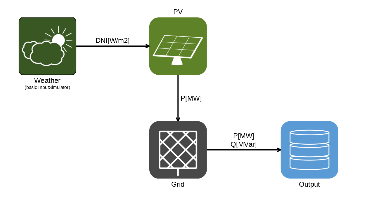
The scenario setup
Important
Setting up mosaik to run in a Jupyter notebook requires an extra step, namely installing the nest-asyncio library and activating it using:
import nest_asyncio
nest_asyncio.apply()
Alternatively, you can use mosaik’s AsyncWorld and let mosaik run in Jupyter’s existing event loop.
See How to use mosaik with Jupyter notebooks for more on this.
Installation of required components
The first step after installing mosaik itself (see Installation) is to install the packages necessary for our simulation.
We will be using mosaik-pandapower-2 and mosaik-pv.
Both of them are available on PyPI, so you can install them using your favorite way of managing Python packages (pip install in your virtual environment, your editor’s Python package management, etc.).
We will also use mosaik’s two built-in simulators: the input simulator as a fake weather simulator and the output simulator to see what’s going on.
Creating a world and starting the simulators
Every mosaik scenario has its humble beginnings in importing mosaik.
We will also be using Python’s random module, the built-in pretty printer, and a function from mosaik.util:
import random
from pprint import pprint

import mosaik
import mosaik.util
We then need to set up a dict that describes all the simulators that we intend to use in our simulation and how to start or connect to them.
This dict is conventionally called SIM_CONFIG.
For our scenario, it will look like this:
SIM_CONFIG: mosaik.SimConfig = {
    "Weather": {"python": "mosaik.basic_simulators:InputSimulator"},
    "PV": {"python": "mosaik_components.pv.pvsimulator:PVSimulator"},
    "Grid": {"python": "mosaik_components.pandapower:Simulator"},
    "Output": {"python": "mosaik.basic_simulators:OutputSimulator"},
}
Each entry in SIM_CONFIG describes one type of simulator.
The key (like "Weather" or "Grid") can be freely chosen by you, the scenario author.
The value is yet another dictionary that describes how to connect to this type of simulator.
For now, we are only using the "python" method, which will run the simulator in the same Python process as your scenario.
In this case, the dictionary has a single key "python" with the associated value specifying the module path and the name of a subclass of mosaik_api_v3:Simulator, separated by a colon.
The documentation of the simulator that you are using should contain this information.
On module paths
The very basic input and output simulators that included in mosaik can be found in the mosaik.basic_simulators module.
The default path for other simulators that are maintained by the mosaik team is mosaik_components.<name_of_the_component>, though many of them are still in other locations for legacy reasons.
Simulators written by you or others can be stored wherever the author prefers, though we kindly ask not to publish them in the mosaik_components namespace.
On type annotations
mosaik comes with support for type annotations, see for example the mosaik.SimConfig in the snippet above.
You can just leave them off if you prefer, but if you turn on your Python type checker, they will often be able to tell you when you accidentally put a typo in your data structures.
We are now ready to create the world. This won’t take seven days, just
with mosaik.World(SIM_CONFIG) as world:
All the remaining code of the scenario will be placed in the with block started by this line. Using a with block ensures that the world is shut down properly even if something goes wrong during the setup.
Within the with block, we have access to a variable called world with which we can start our simulators:
    weathersim = world.start("Weather", sim_id="Weather", step_size=900)
    pvsim = world.start(
        "PV", sim_id="PV", step_size=900, start_date="2023-06-01 12:00:00"
    )
    gridsim = world.start("Grid", sim_id="Grid", step_size=900)
    outputsim = world.start("Output")
The first argument to a call to world.start is one of the simulator names specified in the SIM_CONFIG.
Then, you can optionally specify the ID your simulator should have in the scenario using the sim_id keyword argument.
If you don’t specify the simulator ID, it will be derived from the simulator name automatically.
For example, because we didn’t specify a sim_id ourselves for it, the output simulator will be called Output-0.
All further keyword arguments will be passed on to the simulator.
The simulator’s documentation will contain details about which further arguments are supported and/or required.
In our case, we specify step_size=900 for all simulators except the output simulator.
Note
This step size is a common convention in mosaik as 900 seconds correspond to 15 minutes, which is the market interval on many energy markets.
The output simulator does not need to know the step size because it is event-based, which means that it will run automatically whenever it receives input. (For more information on the different types of simulators, see Measurements and Events.)
In our scenario, we have created one instance of each simulator.
When you need multiple copies of the “thing” provided by a simulator, you can start multiple instances of the same simulator by calling world.start with the same simulator name multiple times.
However, if the simulator supports it, it is usually better to create multiple entities within a single simulator instance, instead.
Entities are the subject of the next section.
Creating entities
Having started our simulators, we now need to create entities in them.
What are entities?
In co-simulations it is very common to want to simulate many copies each of only a few types of things, for example a number of PV systems which are each described by the same formulas (but with different parameters). In the context of mosaik, we call these types models and each copy of them an entity. If you are familiar with class-based object-oriented programming languages like Python or Java, a model is like a class and an entity is like an object. (Technically, this is always true, regardless of whether you are familiar with object orientation or not.)
Each simulator may offer several different models and will usually allow you to create as many entities of each model as you need. All entities created in one simulator will run at the same time during the simulation, but each may work with different inputs and produce its own output. The role of the entity’s model is to describe how the input to (and output of) the entity must be structured.
We use entities because having one simulator calculate multiple similar things at once is usually more efficient than starting a whole new instance of the simulator for each thing. We recommend that you only start several instances of a simulator when you need it to run at multiple points within the same time step or when the simulator does not support multiple entities.
Our highly realistic weather model will be based on random values provided by the built-in input simulator. Furthermore, we will assume that all PV systems are close enough together to be governed by the same weather. We therefore only need one weather entity, which we create by calling
weather = weathersim.Function(function=lambda time: random.uniform(0.0, 1000.0))
This will instruct the weathersim simulator to create one entity of the model Function.
(The generic name Function is because we are using the generic input simulator.
A real weather simulator would have appropriately-named models.)
When creating a Function entity, we need to specify a Python function.
When our the input simulator needs to create inputs to the rest of the simulation, it will call this function with the current time.
The output of the function will be the output of the simulator.
In our case here, we just ignore the time and return a random value between 0 and 1000.
These values will serve as direct normal irradiance in W/m² later.
Data that we pass to a simulator while creating an entity of one of its models is called a parameter or short param of that model or entity.
So in this case, function is a param of the Function model.
Each simulator and model will expect different data as its params. The simulator’s documentation should describe which params are necessary or supported.
Next, we will create 50 entities of the PV model in our PV simulator, so that we can simulate 50 PV systems in the grid.
We could create these entities by calling pvsim.PV(...) 50 times in a loop, but there is a shorter way:
    pvs = pvsim.PV.create(
        50, area=10, latitude=53.14, efficiency=0.5, el_tilt=32.0, az_tilt=0.0
    )
By using the create method, we ask the simulator to create several instances at once.
The first parameter to create the number of copies that we want to create.
All further arguments are params of the model.
In this case, we specify the area of our PV systems (in \(\textrm{m}^2\)), the latitude where the system is placed, its efficiency and the angles describing how it is tilted in space (in degrees).
When using create to create several entities, all of them will have the same values for their params.
If you want each entity to have different params, you will need to write a loop, after all.
However, create is often a useful shortcut because each of the created entities can still have unique connections.
Now, we create the grid by calling
    grid = gridsim.Grid(network_function="create_cigre_network_lv")
    pprint(grid)
According to the grid simulator’s documentation, providing the network_function keyword argument here will result in a Grid entity based on the function create_cigre_network_lv from the pandapower.networks module.
Here, we get to see another feature of entities: they may have children, which are additional entities created automatically when their parent entity is created.
In the case of grid, the children are all the grid elements like buses, lines, loads, transformers, and so on, that make up the grid topology that we specified when creating the grid entity.
Why child entities?
In the case of a grid topology, a description of the grid usually already exists in some format directly readable by our grid simulator of choice. If we wanted to create entities corresponding to all the elements in the grid in our scenario script, we would then end up parsing that format only to pass the data to a piece of software that would have been much better equipped to parse the format itself. As this would be unnecessarily cumbersome, we ask the simulator to do the parsing itself by referencing the file (or similar) describing the grid.
However, we still want access to all the different elements in the grid so that we can connect other entities of our co-simulation to them specifically. For this reason, mosaik allows simulators to return additional entities to the ones that were requested explicitly. These additional entities are called children of the requested entities.
So we have an entity grid that represents the grid in its entirety.
It has children, representing all the elements in that grid.
They can be accessed via grid.children and if you print this, you will get a long list of objects each looking like this:
Entity(full_id='Grid.Bus-0', model_mock=<mosaik.async_scenario.AsyncModelMock object at 0x76c35ba01350>, children=[])
In order, each object’s fields are:
The simulator ID (
'Grid')The entity ID (
'Bus-0')The simulator name, as given in your
SIM_CONFIG('Grid')The model of the entity (
Bus)A list of that entity’s own children (
[])The internal object representing the connection to the simulator
We can use these fields to filter the list for the entities that we want.
We want to connect our PV entities to buses, so we only want entities of type Bus.
We also want to connect our PV system to a low-voltage bus and not to any of the medium-voltage buses that represent the connection to the external grid.
Luckily, the pandapower adapter reports the nominal voltage of each bus as so-called extra info, which is stored under the key "nominal voltage [kV]" in the extra_info dict of the corresponding entity.
We can filter for the buses we want by looking for buses with a nominal voltage of \(0.4\,\mathrm{kV}\) (i.e. \(400\,\mathrm{V}\)), like so:
    lv_buses = [
        entity
        for entity in grid.children
        if entity.type == "Bus" and entity.extra_info["nominal voltage [kV]"] == 0.4
    ]
We also want to read off the real and reactive power values that result at the connection to the higher grid levels.
This connection is represented by the ExternalGrid entity.
We could filter the list of children for entities of this type and then choose the first (and in this case, only) one.
However, I happen to know that that entity’s ID is ExternalGrid-0, so we can use the children_dict field to access it directly:
ext_grid = grid.children_dict["ExternalGrid-0"]
Finally, we create a Dict entity in the output simulator which will store the simulation results for us:
output = outputsim.Dict()
Connecting everything
The last step in setting up our simulation is to spin a web of connections between our entities.
First, each PV system needs access to the weather data:
    for pv in pvs:
        world.connect(weather, pv, ("value", "DNI[W/m2]"))
We loop over all elements of our pvs list.
For each pv we establish a connection from the weather entity to the pv entity.
To do this, we need to specify which attributes should be connected.
In mosaik, attributes, or attrs for short, are (the names for) the values that are exchanged while the simulation is running, as opposed to params that are used during setup.
Here, we connect the value attribute of the weather entity to the DNI[W/m2] attribute of the pv entity.
(Having the units as part of the attribute name is a somewhat common convention.)
The simulator’s documentation should list the attributes of its models, whether they are used for input or output, and in which format they expect or provide their data.
Next, we want to connect our PV systems to the grid.
In this example scenario, we don’t care about the precise buses, so we can use the function connect_randomly from mosaik.util.
It takes two lists of entities and connects each entity from the first list to one of the entities from the second list, using the specified attributes.
It tries to avoid connecting several entities to the same target, if possible:
    mosaik.util.connect_randomly(
        world,
        pvs,
        lv_buses,
        ("P[MW]", "P_gen[MW]"),
    )
The p_mw (real power in MW) attribute of each PV system is connected to the P_gen[MW] attribute of its randomly chosen bus. The gen suffix in the attribute names of the pandapower adapter says that these attributes follow the generator convention (i.e. power generation is positive).
Finally, we want to see how our PV systems influence the power levels at the external grid. Therefore, we connect the ExternalGrid entity that we extracted above to our output simulator:
world.connect(ext_grid, output, "P[MW]", "Q[MVar]")
This looks very similar to the calls above, but note that the attribute names are not given as a pair.
(There are no parentheses around "P[MW]", "Q[MVar]".)
This is actually a combination of two shortcuts in mosaik’s connect method:
In case that the names of the two attributes that you want to connect are identical, you can just give the name of the attribute as a string once (instead of a pair of two strings). mosaik will then use this name for both the output attribute of the source entity and input attribute of the destination entity.
The
connectmethod is variadic in the number of attribute connections. By giving multiple attributes (or attribute pairs), connections are established between all of them.
So in this case, the P[MW] output attribute of the ext_grid entity is connected to the P[MW] input attribute of the output entity, and likewise, the Q[MVar] output attribute is connected to the Q[MVar] input attribute.
These shortcuts make things slightly more convenient whenever attribute names happen to line up. In the case of the output simulator, we can have it this way because it will accept input on any attribute and just store the input under that name in a dictionary.
Running the scenario
We are now set to run the scenario. This is done using the world’s run method, like so:
world.run(until=3600)
Given our convention of 900-second steps for all the simulators above, this will actually run 4 simulation steps at times 0, 900, 1800, and 2700.
The given until time is already excluded.
Finally, we can extract and print the output from our output simulator, by calling the output simulator’s get_dict method, still within the with block that began with the creation of the world.
    result = outputsim.get_dict(output.eid)
    pprint(result)
This concludes the with block.
At this point, mosaik will shut down all the the simulators that it started and close the connections to all simulators to which it connected.
Calling further methods on these simulators is then no longer possible.
Where to go from here
We have now seen how to set up a very small example mosaik scenario. How to progress further depends on your goals when using mosaik.
If you want to build scenarios to answer your own questions, using existing simulators, you can look at our ecosystem page to see what is available. There are simulators for more different types of units to connect to the grid, and also more sophisticated simulators for input and output (for example, reading from CSV files or writing into a database).
When your simulation setups become more involved, you will need to deal more explicitly with the distinction between time-based and event-based simulators, and with hybrid simulators. Measurements and Events contains background information on this. How to simulate at different time scales tries to explain how to create more involved setups in practice.
If you find simulators you want to use, but they are not quite compatible with each other, you might be able to fix this using transform functions. Maybe you also run into other problems, in which case our troubleshooting section might help you.
Last, you might be interested in implementing your own simulators, or in adapting simulators that you already have to use them with mosaik. If so, the next tutorial is for you.
If you run into problems with any of this, you should feel free to head over to our GitHub discussions. All levels of questions are welcome there.